Instruction of DMX Controller GFC006
SKU:GFC006
Accessories:
1.1PC DMX controller box
2.1PC Antenna
3.1PC 7V2A DC
4.1PC XLR Cable
Weight: 3.4KG (Controller Box + Antenna)
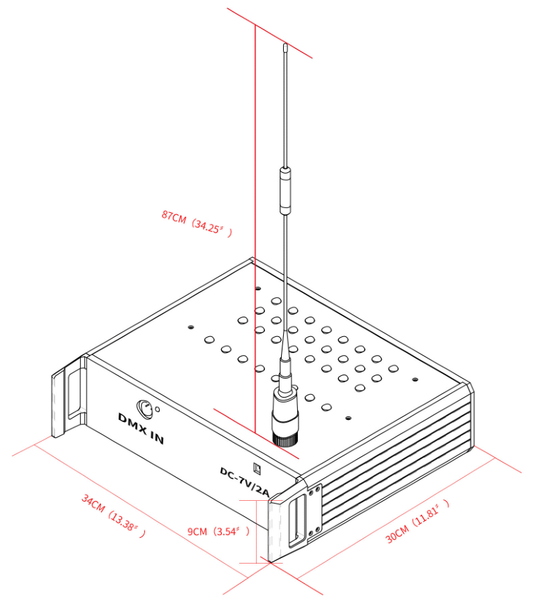
Image 1
3 Steps to Assemble the Controller:
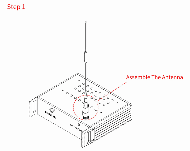
Image 2
Note: Must Assemble the Antenna before Connect Power. Pls DO NOT Try to Disassemble the Antenna into Two Smaller Pieces, It will Affect the Controller Frequency.
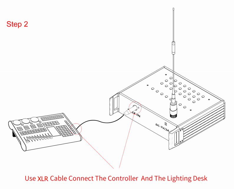
Image 3
Note:If do not Need Use DMX Control, No Need Connect the XLR Cable.
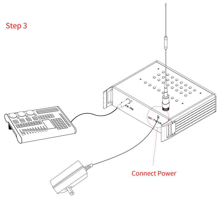
Image 4
Function Table:
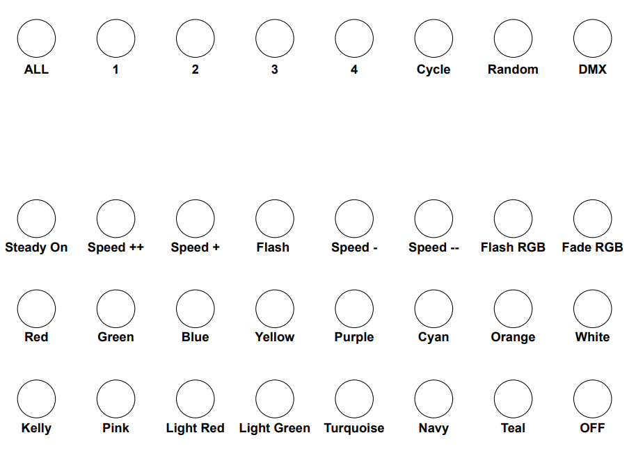
Image 5
The Controller Has Two Modes.
1.DMX Control Mode
Press the “DMX” Button ,the Button Lights Up Red ,Now the Controller is in DMX Control Mode, the Rest Function Buttons are Useless, the Controller can only be Controlled by DMX512 Lighting Board or DMX512 Computer Software. Set the Address of the Controller Accordingly, then the RF LED Bracelets, RF LED Wands, RF LED Pucks ,RF LED Lanyard etc. All are Ready to be Controlled.
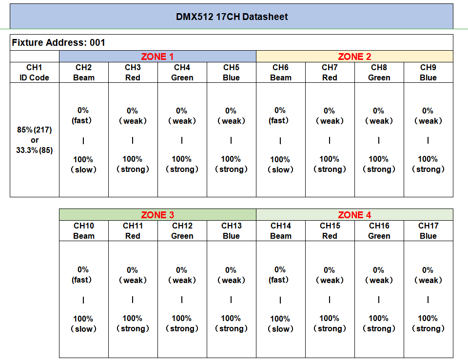
Image 6
2.Button Control Mode
Press Any Button in the First Row (refer to Image 7) Exit the DMX Mode ,Now the Controller is in Button Control Mode and the DMX512 Lighting Board or DMX512 Software not Able to Control the RF LED Bracelets, RF LED Wands, RF LED Pucks etc. ,Only the Button Functions Work. Now You Can Choose any Group #, LED Color, Speed etc. on the Function Table to Get Different Lighting Effects.

Image 7
Function Buttons User Guide:
“Cycle” Means Auto Cycle the Function in Row 2 (Refer to Image 5) ,You can Choose the Color to Cycle the Functions .
“Random” If the RF Controllable LEDs You Ordered is Single Group, the Controller will Random Cycle the Function in Row 2 (Refer to Image 5), if You Ordered Multi Zones RF LEDS , All the LEDs will be in Random Functions.
“ALL” Press and Hold This Button for 5s, the Indicator Light of the Button Keep Flashing, Now the Power of the Controller is Switched from 1W to 7W. Press and Hold This Button for 5s, the Indicator of the Button Change to Steady On, Now the Controller Power Go Back to 1W. (This Function Used to Change the Controller Working Distance, when You Get It, They are Set as 1W, if not Necessary,no Need Switch the Power)

Leave A Comment